Help for bebox replica

hello all guys and good evening !!!

Let me introduce myself, my name is Christian Rosadini … I am an Italian passionate about retrocomputers
Here , in my town, we have an association and together with our friends we do experiments and new projects based on old computers … We wanted to build a replica of the famous BEBOX but we stopped for the Blinkenlights … surfing the internet we found a project many years ago, by an engineer who had reproduced the led display system

http://www.switkin.com/software/geeklights/progress.html

We have electronic engineers who would have no problem replicating the scheme, but unfortunately we are unable to drive the software part …We tried to contact the author but for now we have not received a response … we would like to implement this feature to make our replica absolutely equal to the original…in simple terms it works like this … the program reads the CPU workload and transmits it through the parallel port with a 4 bit code (I assume) … since, at the software level, we are not able to understand how it works, we ask the community for help to get out of it

sure of a positive answer
best regards

PS for any writing errors, the fault lies with google traslator :slight_smile:

Pretty sure the code for Pulse is open source… check that for determining CPU usage.

Then you would just need to write to the parallel port whatever values you want. A parallel port is by it’s nature parallel… so just write the bytes you want to it and that is what will be there. I think BeOS had a BParallelPort class in the Device kit… I don’t think Haiku does since there is virtually no hardware that has a parallel port anymore.

I assume you are making an exact replica since most modern PCs have USB instead of even a single parallel or serial port, if I were doing this on a modern PC I would grab a Pic32MX270 (usb serial or HID MCU) + Chipkit for the software. A lower end PIC would work too but that’s just my goto and it doesn’t require using the horrible IDE (Arduino is admittedly horrible also just less so).

483/5000

thanks for your answer … in fact we are creating a 100% faithful replica of the bebox.
we found the source code of “Pulse” which controls the CPU workload but I don’t have the MINIMUM IDEA OF WHAT TO DO … we are not programmers (and we would need it) to know how to send the data to load on the port parallel.
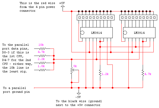
If we take a look at the diagram we see that the LED drivers receive the impulses from the parallel, but we do not know how the impulses are generatedschem1

Yes, for this to work you’d need to send the data to the parallel port, as an 8 bit value with the 4 low bits representing the load for the 1st CPU (in the range 0-16) and the 4 high bit for the second CPU (same range). You could access the parallel port directly using the outb() function (examples for Linux: http://www.embeddedlinux.org.cn/EmbLinux/ch07lev1sec2.htm) or maybe using the “parport” driver on Linux in which case I think it would be as simple as opening /dev/partport0 and writing the bytes to it (as you would do with a regular file) every few hundred milliseconds.

I don’t know if BeOS or even Haiku has a parallel port driver, but the outb method should be workable there.

If you want to replicate the way the BeBox worked - the real hardware had a task that ran on the box and updated the lights. If that program failed, the lights stopped working (other than the disk activity light, which was bottom left and orange with activity.) I was also in the process of making something like this and got as far as ordering the shift registers.

Don’t use a parallel port - they are non existent on PowerPC hardware that runs BeOS and rare on modern PC hardware. Use a USB Serial interface (or get serial to work directly.) The Data you are displaying is, what, 20 bytes of data unpacked? But you could probably send it all as a bit pattern in a single in (4 bytes) + a header (say, 1 byte).

00000000 / 00000000 00000000 / 00000000 00000000

struct
{
byte header,
short row1,
short row2
} lights;

Set header to a value that represents “lights”, e.g. 0x83

You’ll also maybe want to pack the structs as 5 bytes, but that’s up to you. You could make the header in to 2 bytes and that would avoid that issue.

Use the header to set the data type, use the rows to encode the light values. You could also probably pack it all in to 3 - 4 bytes, but then that becomes nasty.

If you are using a PowerPC machine as the host, you could get this to probably work over a Mac serial port with a serial connection. You might need to use some type of serial level conversion for the signals, and the Mac doesn’t really do RS232, but I think you can make it work. If you are using a PC/Intel based solution, then you can just use a USB port and get a USB to Serial driver going - the FTDI chip is pretty well supported and there will be a driver that is open source somewhere I’m sure, if not already in Haiku.

I think the best way to do this is to create an Arduino based board and write a sketch that ties up the IO and drives the lights. Because you could also use the Arduino to create a GeekPort alike connector, but breaking out the digital and analogue pins and feeding the raw data back in to the box. Then you can create more packets for incoming/outgoing digital/analogue data:

struct
{
byte header,
… whatever
} analogueOut;

Again, you can pack the data, but you’ll end up making in more complicated to process.

Having owned a BeBox - the lights are nice looking, but really don’t do anything useful :wink:

There were other projects to recreate the blinkenlights for PC, like PulseBox which uses the serial port:
https://web.archive.org/web/20070814014700/http://www.kaenner.de/NeueSeiten/PulseBox.html

UsbPulseBox
https://web.archive.org/web/20030424232308/http://www.be-in.org/~momoziro/usbpulsebox-e.html

BeLxD
https://web.archive.org/web/20030804050224/http://rob.mitsi.com/projects/beos/default.htm

And if you lose motivation along the way you can always get the official vinyl sticker that was given with one of the japanese BeOS magazine…

Pardon a possibly obtuse observation from someone who knows nothing about hardware …

They’re building the hardware from the ground up. They just need a chip with a device driver. If the parallel port is a good fit, then maybe the easiest thing would be to use a second parallel port chip and the same driver. They will presumably have a parallel port, so if there’s no (PPC?) Haiku driver they’ll need to create one anyway.

Or maybe there are simpler chips that can turn an LED on and off.

@donn they don’t really explain. The BeBox is PowerPC (PPC) and the old Mac line that ran BeOS is obviously also PowerPC. If they are trying to make it work with old Mac hardware and run BeOS, parallel port is seriously out of the water.

On the other hand, if they are trying to make an intel replica (I’d ask “why bother? it’s a fish out of water”, but each to their own), then unless they are using something very old - where are they going to get a parallel port from? They are obsolete. ¯_(ツ)_/¯

So, assuming they are just trying to recreate someone else obsolete design - JUST USE USB!! JUST USE AN ARDUINO!!! An Arduino already has a serial port… you can buy a UNO clone for $5, and it’ll power from USB and provide power for the LEDs!!. With two 74HC595’s, and a few resistors and a couple of other components, you can use a simple sketch to control the LED’s. I think there’s even a library to do it.

@lorezan those projects all would work, but mostly they are a bit obsolete. The first one is even using a PIC, so it’s a more old school version of what I’m suggesting. The second one is creating a device from scratch - probably overkill for this.Last one is a bit thin on info. I’ve seen a diagram using only a bout 3 Arduino pins to generate two banks of circa 10 LEDs, but even using more pins, a UNO dedicated to this could totally run the whole thing I think. If a breakout FTDI board is used, it could also be programmed to have a new Product name and Serial number on the FTDI chip level.

I think I stopped because of COVID19 and also I think I forgot to order more LEDs. But I’ll look again. I think I could probably also get a OLED display going for a modern twist - though my only decent one is currently in my toy Arduino console project (also stalled… lol.)

In my current job I do quite a bit of this type of interfacing (USB, serial over FTDI, Micro controllers) and so can confirm that it is all a lot more feasible and a lot more accessible these days.

thank you all for the suggestions, especially @lorezan … I found the first two projects really interesting and I think they are seriously feasible (also thanks to the fact that the author of the project had also created the lights management program) … of course when we talk about a replica it is peaceful that we intend to insert a modern motherboard in the case of the bebox (equipped with both parallel interface and usb so we can have fun with any scheme)

Is there a website where you document the progress on creating a BeBox replica?

231/5000

we hadn’t thought about it yet … but the idea of creating a blog was in the air … obviously before entering the project we did a feasibility study … for this reason we had run aground on led speech

@Dr_Slump - I would seriously suggest using an Arduino and either wiring a FTDI board (it’s just 4 pins IIRC) or use the on board serial to USB port (which depending on model will not be FTDI.) From what I can see, Haiku supports a lot of USB serial chipsets, according to this ticket on the tracker Haiku Serial, “FTDI, Prolific, Silicon Labs, and standard USB-CDC”. This guy seems to have the Arduino IDE running on Haiku too, and programming the boards. If you do break out the FTDI, a FTDI board like this would work.

1 Like

Ideally USB to serial , and a real serial adapter could work too… just program your device to accept input form both ports.

Also to the original poster… to tackle a project like this you need a programmer or you need to learn, no way around that.

1 Like

or I use projects of other users who have already built it previously
I have NO IDEA of how to program and how to structure the program which should then interface with external hardware … The sites that @lorezan suggested to me are a good starting point … I downloaded the software present in a project and it seems to work well on beos … now I try to build the hardware interface and see how it behaves … if it works as I think, I can say I am satisfied

@Dr_Slump, so

  1. You would need to program a PIC with the binary, so you’d need a lot more hardware to do that. It’s closed source too, so if it doesn’t work or you need modifications, it is dead in the water.

  2. You still need a way to burn the firmware and the chip is a little more obscure.

  3. Has absolutely no detail and assuming the guy responds to your email, you have no way to assess if his design is sound.

So, I’d still say do it yourself. This is pretty much what you want here, and also this thread actually even namechecks the BeBox.

Hello, Dr_Slump! You could try with these ZIP files, they contain the source code and compiled versions of Switkin´s software.
Please upload some photos of your replica and tell us about technical details you are thinking to include in it (motherboard, microprocessor, video card, BeOS version, Geekport, etc). Good luck with your project, keep posting some progress about it, greetings from Argentina!

https://drive.google.com/drive/folders/1c4XkcU90D6skQGjWPEG6LrW9KRFGudMM

The elephant in the room here is that none of this really works anymore. My current machine has an i7 with 4 cores and 8 threads - how do you represent that using blinken lights? The BeBox had 2 rows, one for each processor. Each processor had one core. When you get to 8 logical cores - that’s a lot of LED’s. I don’t know that any of this really scales to anything modern.

My plan is to dig out my old Mac with dual processors (serial) and get this working with that, or maybe the netbook (usb-serial) I have that runs Haiku (I think it has max 2 cores as it is an early Atom.) I have no idea how you can make this scale well on modern hardware with more cores without making it look a bit weird.

1 Like

696/5000

@caleb thank you very much … what you linked to me is what I was looking for … in the meantime the author of the program (Daniel Switkin) had also contacted me who had provided me with the source code of the program … unfortunately I am not able to compile it because as a programmer I am a dog and I did not know where to start … but the files you passed me are EXACTLY what I was looking for … I am starting to write the blog of the creation of the BeBox (Daniel asked me too) … in a few days I’ll put the address here so you could see all the progress I make … unfortunately I do it in Italian ( however you have google traslator :slight_smile:

Maybe have one side for cumulative or average CPU load, then another side for disk access? There might still be a way they could put Blinkenlights on here without being limited to 2 processors or cores :slight_smile:

To replicate the bebox, I use old motherboards that do not use multicore technology (in fact, I found an old 800 mhz dual processor pentium III card and I think it will be on that hardware that I will run beos on).
The blinkelights will work exactly like in the original bebox, monitoring the activity of the two processors.

I also created a section, on our association page, where I gather all the progress I will make in the construction

https://www.classicdevicesclub.it/category/bebox/

follow me … we will see some beautiful !!!