Help for bebox replica

In 1998 there was a contest made by Plat’Home, the BeOS distributor for Japan, to design an Intel version of the BeBox.
The winning entry was presented at BeaCON1, and was described in a BeOS special edition of the japanese magazine PCWAVE.
The proposed specs:
https://web.archive.org/web/19990902232305/http://www.plathome.co.jp/BeOS/kanren/bebox/result/index.html


And the picture of the stickers to turn your boring beige box into a blue marvel, from another magazine, for the curious people:
000b

7 Likes

@apgreimann disk access was shown by the bottom led on the left side on a bebox. I think that should still be the case for any new design

So I made this:

image

I also verified that the Arduino UNO is seen by Haiku as a USB Device and that I can connect and receive serial data from Serial Connect application. The rest is really just coding. It uses one arduino Uno, 8 220 resistors, one 10mf Capacitor, and two 74HC595 16 pin dip package shift registers. That gives 16 LEDs in two banks of 8. I could probably make it 10, but that would make the data a bit more complicated to bit shift. Seriously, I followed one tutorial (I linked above) and watched one YouTube video.

I think using 3 more pins, you could make 2 banks of 16 LEDs without making the data complicated.

Serial data wise, this it two bytes of data per cycle, and doubling would mean circa 4 bytes. If you used 10 LEDs in each bank, you could use the other bits to identify the bank and also probably a disk access light too.

1 Like

I don’t want to work with Haiku but with BeOs … and surely this project would not work since BeOs does not recognize USB…it is undoubtedly an interesting project but it is not what I am looking for

@Dr_Slump so, yeah - this can work with BeOS over serial but probably needs a TTL chip to make that happen due to voltage differences. But BeOS did have USB… and there were USB Serial drivers available because that’s how a lot of the BeIA developers debugged the devices.

For me, a modern BeBox would run Haiku… because getting BeOS to run on modern hardware is next to impossible these days. If you want it to be authentic - use an old Mac logic board - because that’s what a BeBox was PowerPC. You can buy an old 9500 or 8500 logic board for under €100, and a complete machine for less that €150.

If you want to make a modern homage - I think using BeOS seriously limits you. You’d probably get a better experience out of Zeta, rather than R5.03. I guess you could also try Dano, but even that isn’t R5. But honestly, I couldn’t get Zeta R1.21 to boot on the same hardware I boot Haiku on… and that is an old Atom based Netbook… it booted to a grey desktop with nothing else and so I gave up at that point. R5 would go nowhere near booting and all of the hacked up R5 editions are probably gong to have the same issue as Zeta.

Good luck - I think this is a great idea - just don’t really agree with your direction.

You are welcome, @Dr_Slump. I will be following the blog, it is a
project that any BeOS enthusiast love and appreciate.
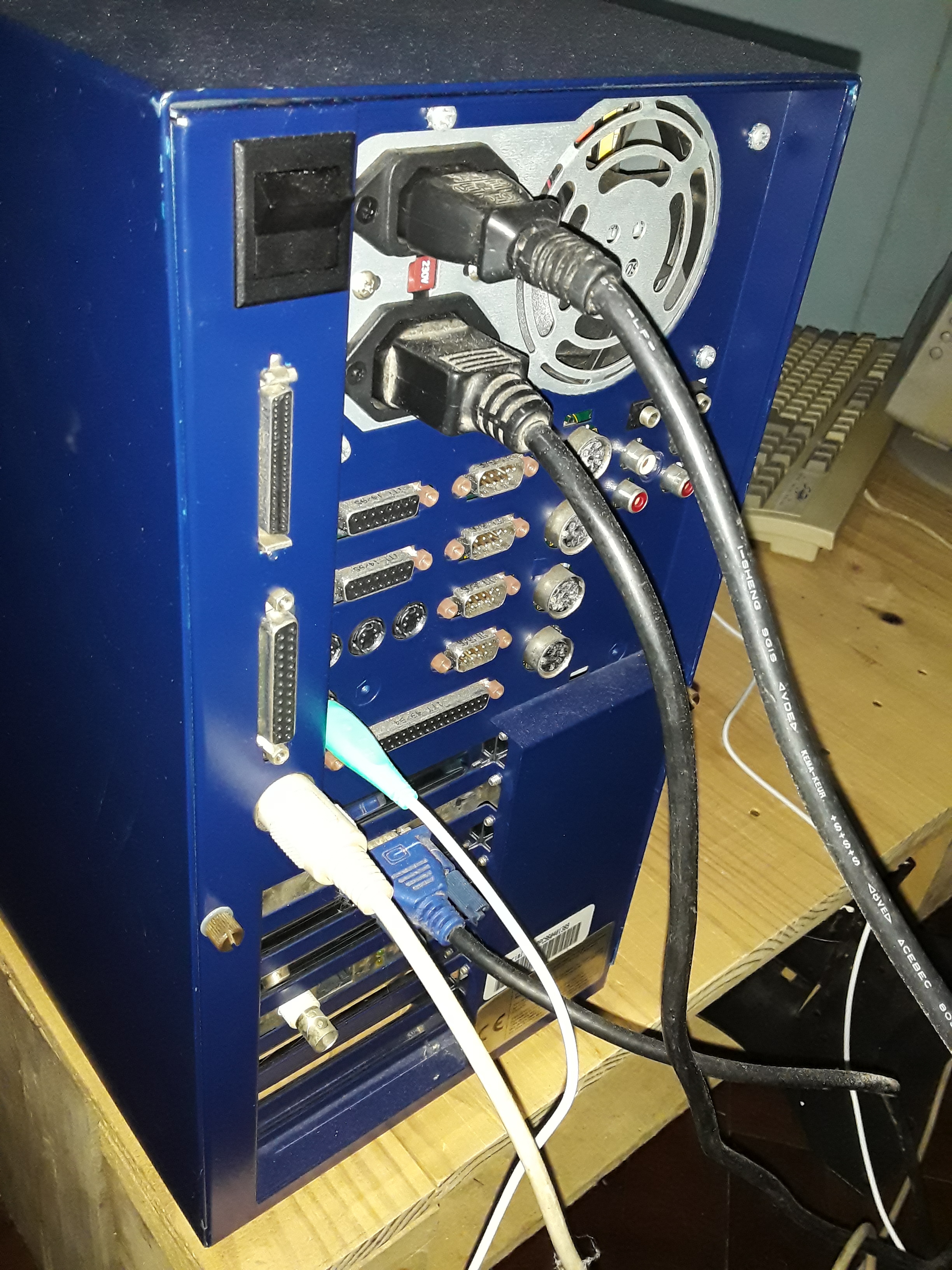
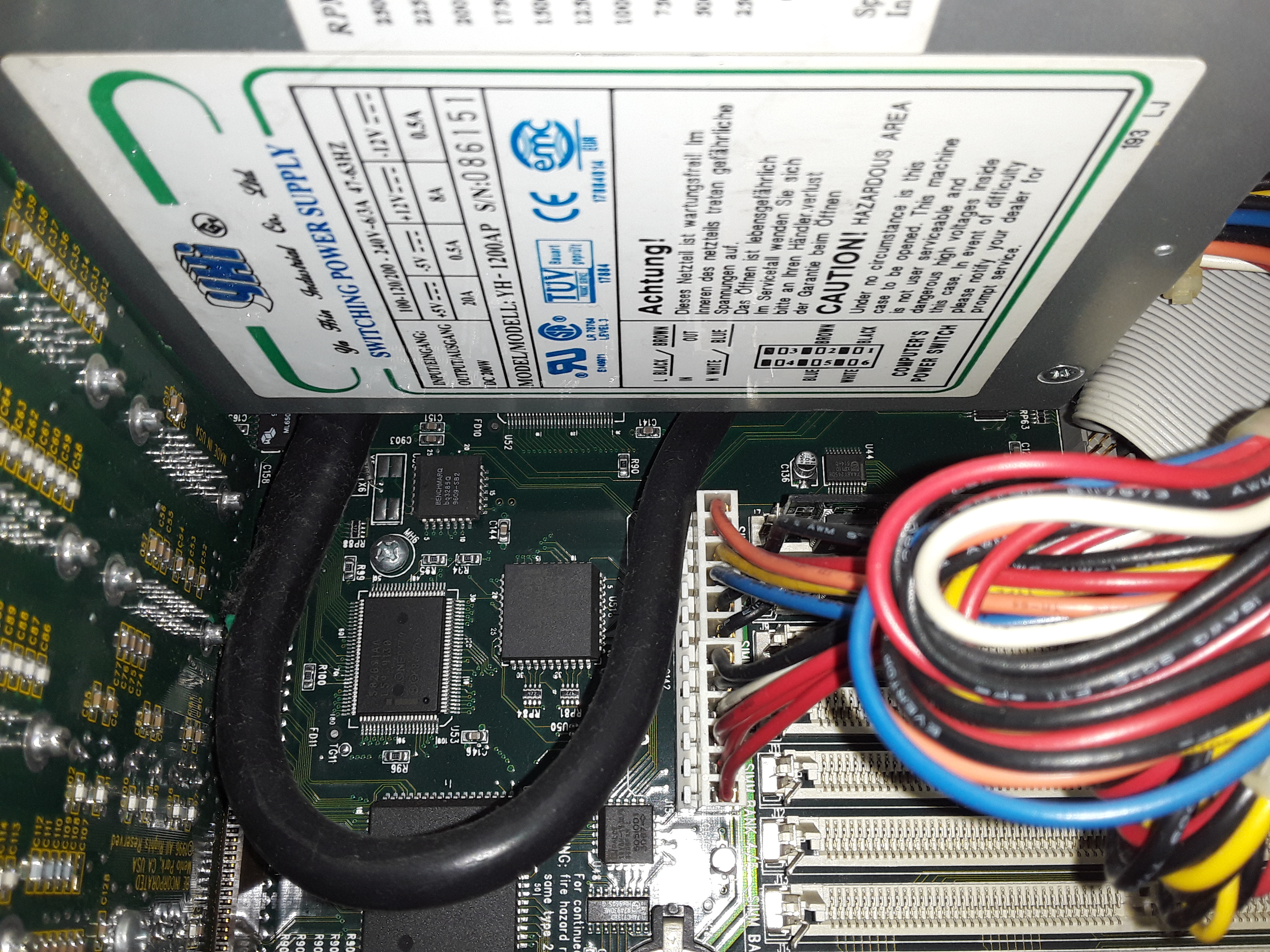
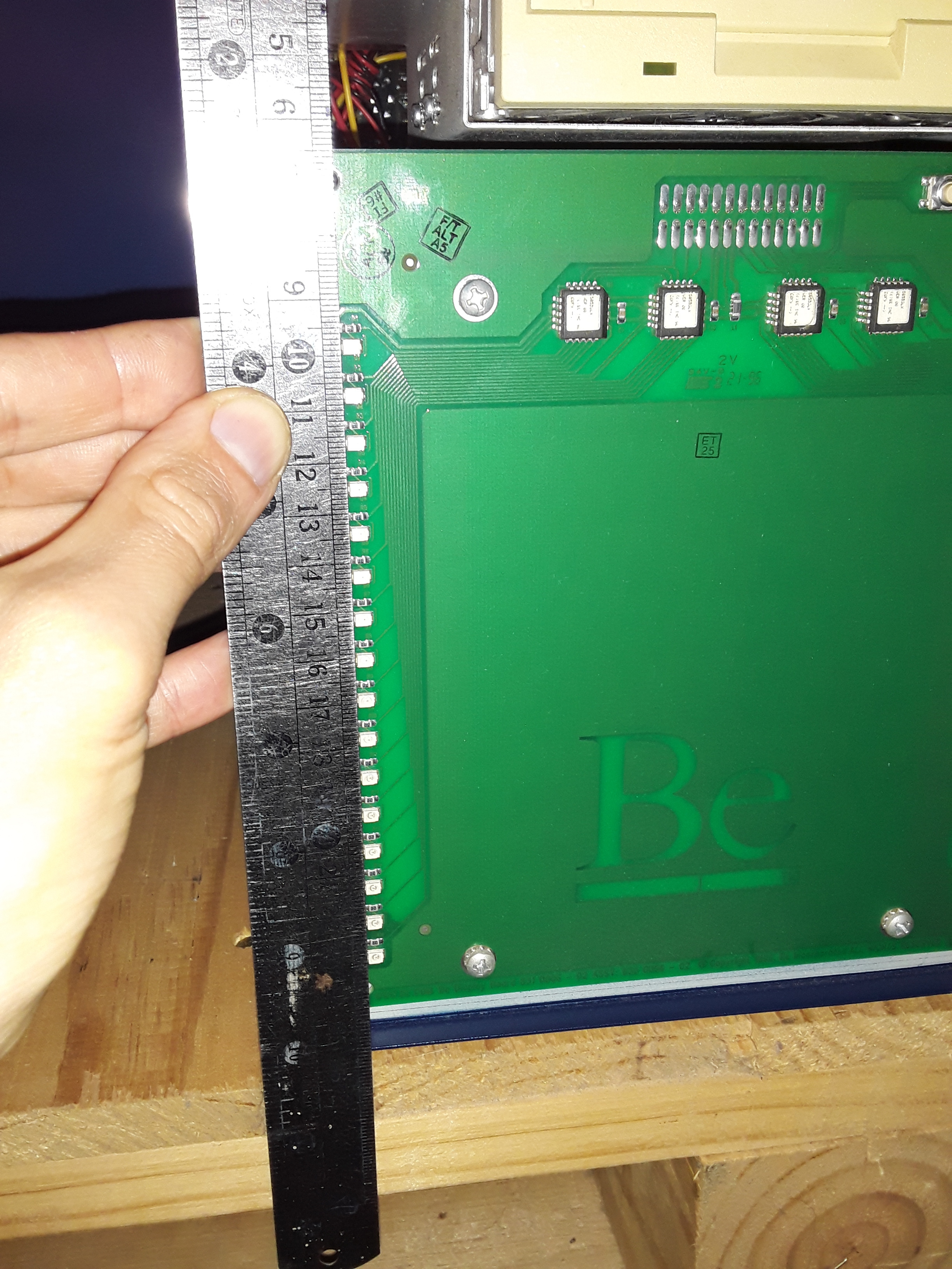
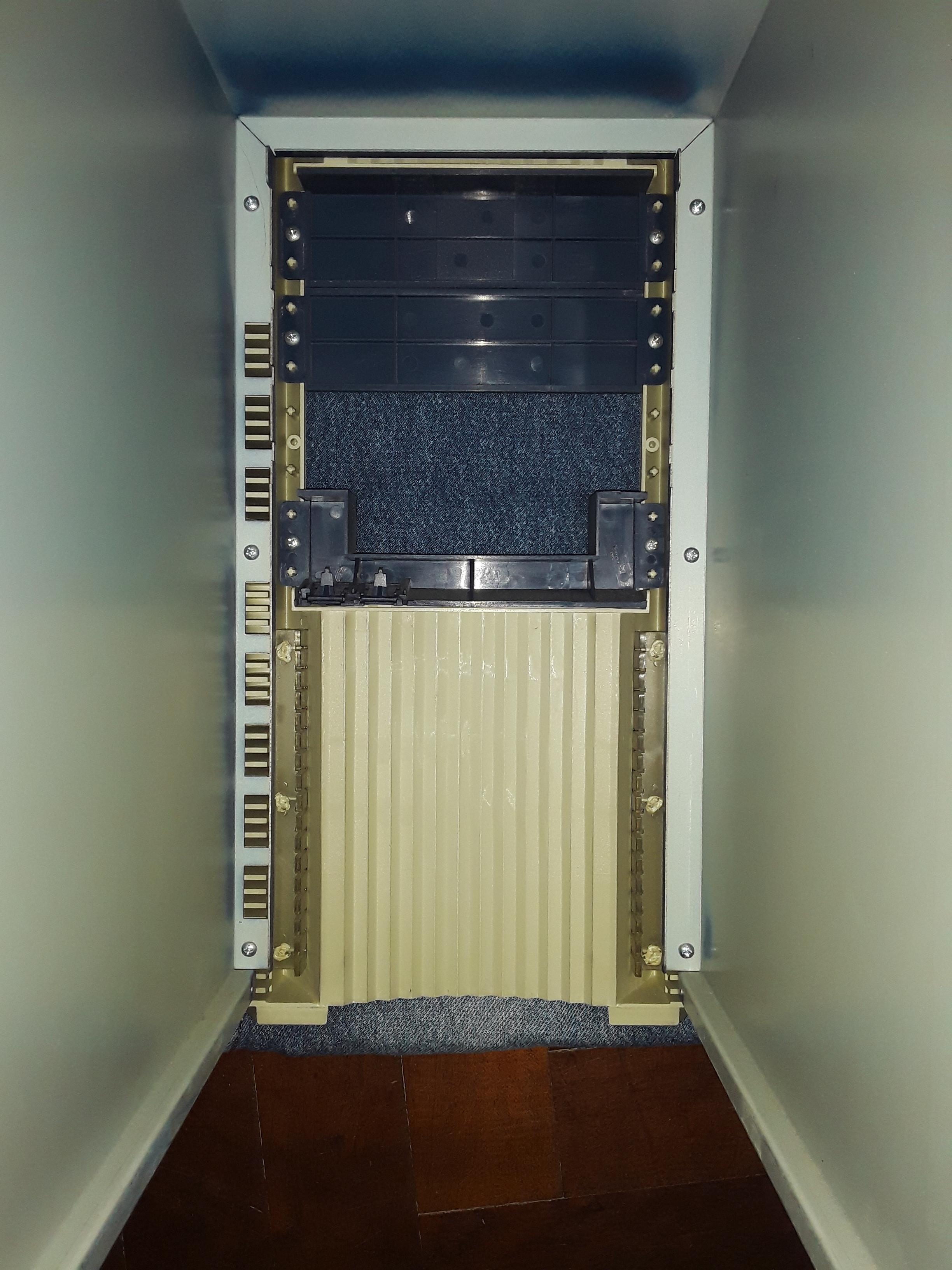
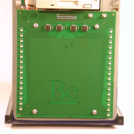
In case you need, I have a real BeBox (133 MHz version), I could send you photos of any small details or inside boards, or take some measures in millimeters or inches, just tell me anything you need to reproduce the legendary BeBox.

I also buit an “Intel BeBox” many years ago, which I still using it with BeOS! It includes an Epox KP6-BS motherboard with dual Pentium 3 550 MHz slot 1 microprocessors, 512 MB RAM (PC100, 4 x 128 MB), an AGP Matrox G400dualhead (one video output per person is not enough :slight_smile: thank you @rudolfc for amazing drivers!), a BT878 analog video capture card and TV tuner, Firewire 1394 controller card (Texas Instruments chip), a DEC chip based PCI ethernet card
(the great Digital Equipment Corp!!), an Adaptec SCSI adapter PCI card, AWE64 Isa sound card and an ISA data acquisition card (Geekport like!).

I also have a PowerMacintosh 4400/200 MHz to run BeOS 5 PPC software.

So three “BeBoxes”, the original, the “Intel BeBox” and the “Apple BeBox”.

I really like that you chose BeOS for your project and x86 hardware from the late 90s and early 2000s (BeOS era!). As @memsom says, BeOS has USB support and drivers but I would also prefer a simple serial RS232 signal for the Geeklights!

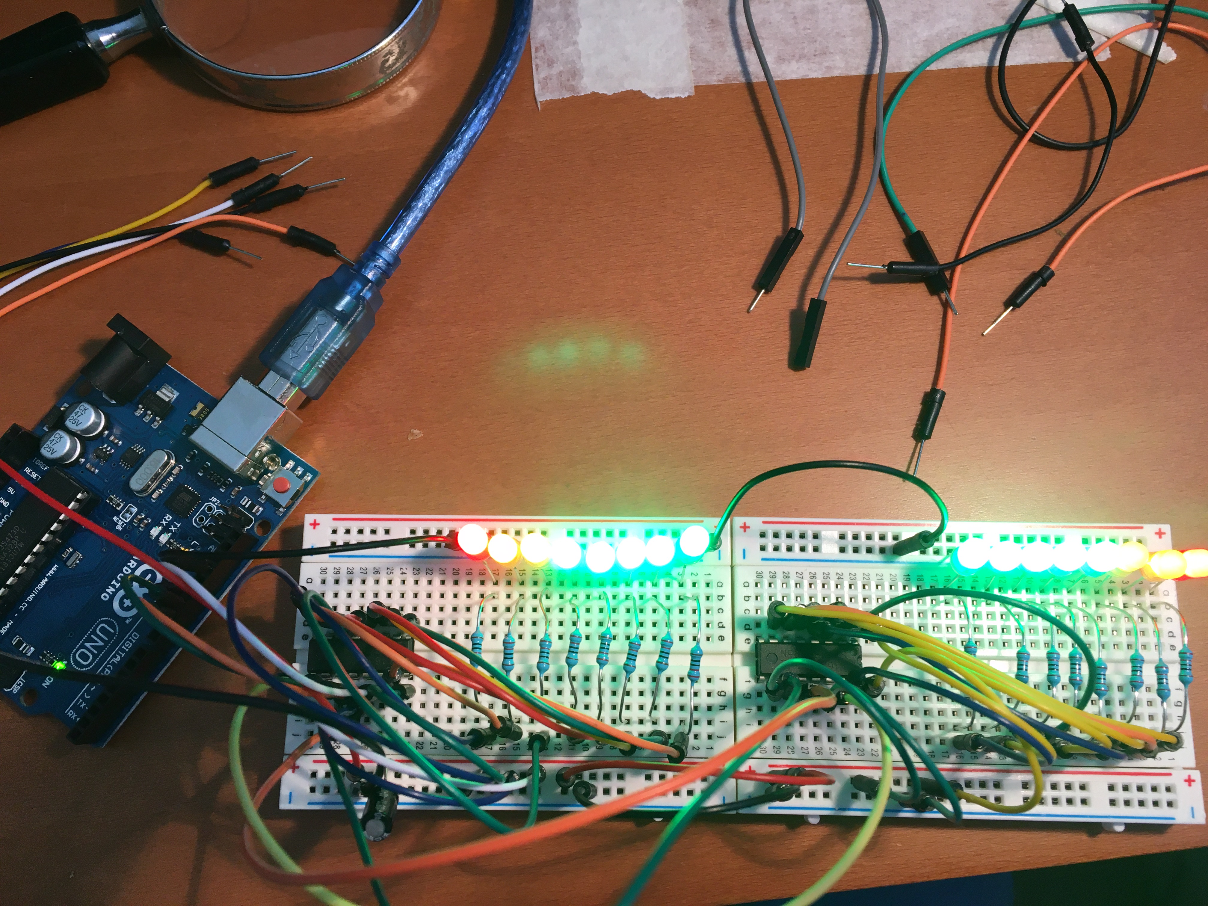
Nice to see new Geeklights Arduino based project by @memsom! Please, share schematics and code, it could also be used for Haiku!

The links and information provided by @lorezan are so interesting, I really love that kind of links luckily preserved by the Internet Archive! @lorezan, please, keep always posting this kind of historical delightful references!

Much luck with the project, I will be following it, just ask for anything you need to make it concrete!

After you finish your beautiful BeBox replica, future versions could be based also in another architectures (PPC, ARM, SPARC, etc) and could run Haiku or also another OS like Plan 9, NetBSD, etc.
Check this: https://web.archive.org/web/20110812075117/http://bebox.nu/os.php

1 Like

Ah, BeBox.nu was one of my old haunts!

So, I was trying to work out the LED config on the front panel, and this image confirms it:

lights512x512

16x on each side, plus there’s a 17th for the hard disk activity. So, that was what was holding me back doing this properly… Also - in that image, looks like 4x shift registers!! Hah!

It would work… you would merely have to adapt the code to read from one of the UARTS instead of the Virtual Com port USB UART… which is indeed trivial. There is no reason to do it the same way they did it… at all these days and it will just make it more difficult for other people to use.

Even a 1200baud serial line could drive that display at 33.3 FPS.

thanks @caleb for the support (it’s important when starting a new project)
We will see later how to “equip” the bebox hardware
I have a motherboard with 2 800 Mhz pentium III processors, an awe 64 sound card, 3COM network card, also I would like to put a dual processor (spectacular) MAtrox G400 video card that I have in my baskets full of cards.
One thing I wanted to ask you … the bebox is powered by the button on the back of the computer ??? because I have not seen power buttons on the front panel … About the front panel I ask you a favor … you can take more detailed photos like the one that put @memsom … I need to know how much is the distance between led and led and the measure of the same in millimeters… because it is almost certain that I will have to put the led on a breadboard to make them spaced at the right point.
Also for @memsom, as @caleb said if you can put the schematics and the source code for arduino and the software for haiku because it’s something I want to work on apart from this project

I would suggest you use an older AGP Nvidia card… since you can actually get better drivers for those on BeOS that RudolfC wrote.

http://rudolfs-place.nl/BeOS/NVdriver/

A Geforce 2 Ti is probably want you want going from his last set of benchmarks GeForce2 Ti, MX4000 might be faster since he says that but I’m not sure if he meant faster as it fastest card supported or fastest actual performance.

@Dr_Slump whatever I do I’ll do a write up and provide the details. Nothing I’m doing is particularly hard, I think you can do it all yourself very easily. The only part I don’t have working is the serial link under Haiku/BeOS, and I think that should be quite trivial. USB will be the first target. But if my Mac 9500 still works and I can get it from storage, I’ll have a go at wiring that up too.I have an adapter for an old Palm Pilot, so that should have the bi-directional serial mapped to the Mac serial port and a DB9. Probably a Modem cable too.

The sizing I don’t know. I don’t have a BeBox anymore. I sold mine in about 2007/2008. But I can tell you - I believe the power switch on the back turned on the computer. This bit is important (to get a real feel for the BeBox). the POST was as follows:

  • Turn on power - screen is blank and stays blank till the logo appears below… there is no BIOS and no way to do anything with the BeBox till it gets to the logo stage.
  • Memory test… for each stick or RAM, Blinken lights count up on left side (0 - 16, 16 - 0) and then right side (0 - 16, 16 - 0) quite slowly (each side takes 10 - 15 seconds to complete) . It really can take about a minute to boot with quite a bit of RAM.
  • lights stop (might flicker a couple of times)
  • hard disk access starts (blinken light now measure the cpu load like normal - they work from the point the BeBox starts booting - that is probably important to note…)
  • the animated 3D Be Logo appears (at this point, if you hold space you get a very, very basic boot menu that really only lets you pick a boot volume - INTEL had this same boot menu circa R3.x.)
    1_4PIvg6xO7RabgZbW5dH1AA
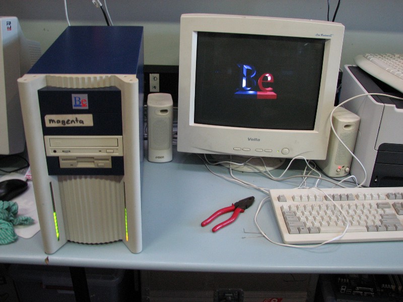
. What you see on Intel never happens - you do not see the boot screen with the circles, you basically see this: BeOS PowerPC booting with boot menu or BeOS PowerPC booting (no boot menu) (this is on a Mac, but it was very similar on my BeBox, just without the Mac bits prior to this.) You might want to watch the rest of the video, as it shows a leaked version of post R5.03 for PowerPC too.
  • The desktop appears
  • Tracker loads

So, it was quite different. The closest you will get to authentic is using a Mac motherboard and the hacked boot disk Mac loader (that basically doesn’t load a full MacOS, it just loads a floppy sized stuf and immediately runs the BeOS loader app. Nathan Whitehorne had a faq on how to do that, which is still on the BeTips server)

2 Likes

@Dr__Slump, I opened the BeBox and took some photos, here is the information you requested! :slight_smile:

  1. Yes, the power switch is located on the back of the computer, upper left side exactly (check the black switch).

20200428_205533
The BeBox uses an AT power supply not ATX:

20200428_212220

  1. The distance between the leds of Geeklights is 6.35 mm (exactly 0.25 or 1/4 inches).

20200428_210917
I also include a photo of the inner side of the case, so you have an idea of how it looks like near the Geeklights PCB.

20200428_211556
Interesting suggestion about the video card by @cb88 but I would insist that you use that dualhead Matrox G400 that you already have, because you could use multimonitor mode and extend your desktop with two monitors, which is a cool feature. On my “Intel BeBox” works perfectly.

Nice blog! :slight_smile: I will be following it! Could you share the 3D model file of the BeBox?

The Nvidia drivers have dual head support… and the hardware is just more powerful… there’s no contest really the Nvidia drivers are the best drivers for BeOS. Read here for complete features list: Be-hold: Haiku unified nVidia TNT/GeForce driver

2 Likes

It is clear that mine will be a replica based on an aesthetic aspect (therefore I want, as far as possible, to replicate the shape of the case) … then it is clear that there will be compromises for everything else (but still on the hardware and software I try to get as close as I can) and especially since it is an aesthetic replica, I want to do the blinkenlights well
@caleb thank you very much for the photos that will allow me to proceed as best I can in the work of positioning the LEDs.
during the week I put more photos of the prototype of the blinkenlights circuit that I am building … if you want the STL model of the bebox give me your email

Because the corona i am sitting at home with my cad workstation. If there is somebody located in germany who have an original BeBox i can measure and model it in 3D. Let me know if you need my help.

@caleb - the only perf board I have is way too small, so my POC will be scaled down. Seems to have 31 x 26 holes, so I think I have enough spacing to make a 2 rows of 16 on the board with a second board containing the rest on the guts. Putting it all on one board would be tricky.

I’m wondering if I could do something with KiCad and get a board made (maybe populated with LEDs, resistors, caps and sockets for the shift registers and other chips)… I think also I can use an MSP430 to run the shift registers as I can easily get that to work without needing to burn bootloaders etc. But I’ll get it to work with an Arduino too. I can then break out the serial lines and replace the serial board with an FTDI one or a custom TTL based one with a traditional DB9 socket.

Let’s see how far I get with making the POC, non breadboard version.

@extrowerk I guess it depends how bored you are, but you can get a rough idea from photos. The interior you can see is going to be a standard 3.5" bay, 5.25" bay opening at top and those plastic rails towards the bottom are what go over the LEDs that are 0.25" apart. It was all based around standard PC case designs. Although the front is custom, you can probably start to extrapolate some of the dimensions from the info you have. It won’t be exact, but you could make something close and refine it as you get more data.

There are some more reasonably high res shots here on Joseph Palmer’s bebox page (He designed the logic board.) You could try looking at the wayback machine “bebox.nu” archive too, as that had a lot of details.

If you look at the images,you can see things like - standard PCI slot covers, standard PSU connectors, standard port sizes… if you can get those dimensions, you can get a lot of the sizing without the need for more detailed measurements.

Dr_Slump, will you add working Reset and Interrupt buttons to your replica?

for all those interested in following the construction of my BeBox, I have inserted the STL model on our association’s website so you can tell me (who has the original machine) if there are errors in the measurements

https://www.classicdevicesclub.it/wp-content/uploads/2020/04/bebox-stl.zip

meanwhile I am moving forward with the prototype of the blinkenlights and when the LM 3914 arrive we do the general rehearsal

really no … I wanted to turn on the machine with the switch from behind like the original